Overview
I designed a novel single-piston pneumatic engine and fabricated a functional proof of concept entirely out of laser-cut clear cast acrylic. The engine mechanism is inspired by the table engine, a stationary steam engine variant with a distinctive transmission configuration.
Mechanism
The cylinder is positioned vertically on a table-shaped base. The piston rod extends from the top of the cylinder and connects to a cross-bar, which is constrained on either end by linear slides. Parallel connecting rods transmit the reciprocal motion of the cross-bar to two parallel cranks, which are positioned below the cylinder.
The table engine is listed as movement 346 on 507movements.com. For reference, the overview diagram provided on that site is reproduced below:

Applications
The applications of a table engine — much like any source of rotary motion — are effectively limitless; anything which can be coupled to the output shaft of the engine can benefit from its steady conversion of high pressure stream into mechanical power. The table engine was often used in breweries as a means of powering pump systems and in sawmills to rotate large circular saw blades.
On account of its long connecting rods, the table engine was ideally suitable only for low-speed and low-power applications. At high speeds, the cross-axial force exerted on the rod by the crank can induce bending moments that stress the rod in excess of its yield strength. Furthermore, the long rods are susceptible to buckling under large axial loads.
History
The table engine configuration was first introduced by James Sadler in 1798, and was a reflection of the then prevailing belief that horizontal cylinders would experience uneven bore wear due to the asymmetric force of gravity on the piston head.
Despite it’s mechanical shortcomings, the humble table engine gained popularity in the early 19th century because it was considerably cheaper to manufacture than other contemporary designs and could be flexibly sized to meet particular application requirements.
The design of the table engine was quickly overshadowed by much more robust vertical single-cylinder designs. In the Marshall steam engine, pictured below, the direction of the piston is reversed, which allows for a significantly shorter connecting rod.

Consequently, this type of steam engine was suitable for high-speed and high-power applications. Outlined in red is a small rod used to time the input valve on the steam inlet port; the mechanical movement of this timing rod is very similar to that of the table engine. Since this rod is not load-bearing, it can be long and thin without risk of mechanical failure.
Design
The engine is a double-acting single-piston pneumatic engine with a novel fixed-offset valve gear configuration. A double-acting engine produces power during both the upstroke and downstroke; when one cylinder chamber is pressurized, the other is open to the atmosphere (allowing the spent steam to exhaust).
All components must be planar, since the engine is designed to be fabricated entirely of laser-cut cast-acrylic. This led to interesting design challenges, of which the most notable is the square cylinder.
Parameters
There are two main parameters which affect the efficiency and power output of the table engine:
- The length of the crank determines the maximum angle between the connecting rod the crank when the piston is mid-stroke. If the crank is too short, then the connecting rod will not induce a sufficient moment about the rotational axis of the crank to produce meaningful power. Conversely, if the crank is too long, then the angle between the crank and the rod when the piston is mid-stroke will be too extreme, which is suboptimal because a significant portion of the force exerted by the piston on the connecting rod will not be transformed into usable power. The crank length also determines the stroke length.
- The bore determines the maximum force that the high-pressure steam can exert on the piston head. A larger bore allows for higher forces, but requires a greater quantity of steam input to maintain pressure in the cylinder.
The bore and stroke are sized such that the average adult should be able to power the engine with a forceful breath. A complete exhale at an average gauge pressure of 2psi is enough for 5 revolutions.

I used Desmos to animate the motion of the crank, connecting rod, and piston. The animation helped me approximate reasonable design parameters before moving to model the engine. You can view the Desmos graph and modify design parameters here.
Components
There are 34 unique components in the engine. A few critical components with interesting design considerations are detailed below.
Valve
The valve consists of the valve body and the valve stem, which moves sinusoidally within the valve body. Two openings on the valve stem alternatively route high pressure air to the space above and below the piston head. The engine is double-acting; whenever high pressure air is admitted to one half of the cylinder, the other half of the cylinder is open to the atmosphere to allow for the exhaust of spent air.
Valve Gear
The motion of the valve stem is 90-degrees out of phase with the motion of the piston. Since the valve gear is implemented with a fixed train of gears, the offset cannot be changed during operation and the motion of the valve stem is purely sinusoidal. In an actual engine, these limitations would be so prohibitive as to render the entire engine practically useless, so steam engines employed complicated linkage system to allow for variable cycle properties.
The metallurgy and manufacturing capabilities of the steam-engine era limited the use of large load-bearing gears. Consequently, valve gears never incorporated actual gears in their design. While completely impractical, my design is gear based and completely novel. Following the convention of engineers of the era, I have thus named it the “Goldstein Gear”.
Cylinder
The cylinder is a rectangular prism and the piston is square. This design feature is necessary as the engine is design to be fabricated entirely of flat sheets of cast-acrylic. This significantly increased the area of the contact path between the walls of the cylinder and the sides of the piston head, which consequently increased the friction in the system. The seams of the cylinder walls had to be sealed thoroughly with a caulking compound to maintain a pressure differential.
Flywheel
The single-piston configuration, only produces power until the piston head reaches bottom-dead-center (BDC) or top-dead-center (TDC). At BDC and TDC, there is a momentary lapse in power as the valve stem reroutes high-pressure air from one end of the cylinder to the other. A flywheel stores rotational kinetic energy, and forces the valve stem and piston to continue moving until high pressure air is admitted into the opposite cylinder chamber and power production is resumed.
Efficiency
The engine is designed to operate with a gauge pressure of 2 psig so that a human breath can power it without straining the lungs. This provides barely enough force to move the piston, and so this pressure must be maintained throughout the entire intake.
During the intake portion of the cycle, a conventional steam engine does not admit enough steam to fill the entire cylinder. The working pressure of a steam engine may be as high as 100 psig, so once the inlet valve is closed the steam in the cylinder works expansively to push the piston head as its pressure decreases. Less steam is spent each cycle and more of the energy spent compressing the steam is converted to work, resulting in a more efficient engine.
Since my engine design does not allow for expansive work, it is highly inefficient when run at a gauge pressure higher than 2psig.
Fabrication
Once I had a general idea of what the engine would look like, I modeled each component in SolidWorks. Since the fit of components was important, I used a master-modeling technique. There was a single file acting as a single-point-of-truth from which other SolidWorks files inherited critical design features. Each component is in its own parts file, which allowed for convenient fabrication and digital assembly.
Before producing any physical components, I assembled the engine within SolidWorks and performed a motion study to ensure that there was no conflicting geometry.
Once I confirmed the viability of the engine design, I laser-cut each component from clear cast-acrylic so that the internal components would be visible. Certain components are made from 1/4 inch acrylic, while others are made from 1/8 inch acrylic.

The final engine has additional components not pictured above:
- thin steel rods used as axles and shafts
- thin steel rods used to friction fit component together to avoid glue
- spacers underneath the gears and flywheel to reduce friction
- Additional flywheel layers to increase flywheel weight
- Additional valve body layers to raise the valve stem opening
There was a great deal of friction in the engine, so I had to carefully sand certain components for optimal clearance and lubricate high-friction surfaces with silicone lubricant.
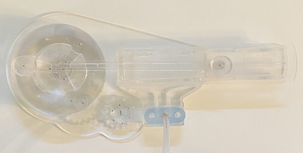

Proof of Concept
After hours of research, design, and fabrication, I had finally created a working engine. See the below videos for some action shots.